このサイトのコンテンツは個人の意見で会社を代表しーひん
概要
The high level view is that the screen is covered by 8×8 pixel tiles. A triangle setup block takes in triangles, culls ones that are fully offscreen or backfacing, calculates the edge functions and AABB, and then passes that information to a tile distributor that distributes triangle-covering tiles to rasterizers depending on the coordinates of the tile. There are 16 rasterizers, each processing eight rows of eight pixels at a time, and therefore tiles finish in 8 clocks, assuming no backpressure from the pixel FIFOs. Rasterizers are also responsible for tiling data before writing, in the case of non-linear render targets. This is because texturing is forced to use a specific tile mode, and I wanted to support render to texture. Render target width can be any power of two between 32 and 512, or 640 in the fullscreen case. Height is the same, except it’s fullscreen value is 480.
Compare this to the previous rasterizer, which was a “tile racing” design. A 640 wide screen was covered by a row of twenty 32×32 tiles, and each tile was handled by a rasterizer. It was similar to beam racing in that you had until HDMI scanout finished the previous tile row to rasterize triangles. Rasterizing to dedicated BRAMs was a great way to not have to deal with DDR3, but it was limiting in terms of performance. The design also didn’t support texturing, programmable render target sizes, tiled render targets, and a large offscreen buffer area to avoid having to clip triangles that were partially offscreen.
I am currently targeting 200MHz but thinking 150MHz is more realistic.
Terms and Definitions
Confession: I am garbage at deciding on terms to use and sticking with them, so parts of this blog post may deviate a little from what I use here, but I figure its still useful to at least pretend I am consistent.
- Rasterizer: an 8 pixel wide adder that calculates edge functions, tests which pixels are inside the triangle, tiles data, and exports
- Screen Tile: an 8×8 pixel tile. A 640×480 render target would be covered by 80×60 screen tiles. Each screen tile currently uniquely maps to a specific rasterizer
- Row: primarily used to mean one 8-pixel row of a rasterizer or screen tile, but occasionally refers to a whole render target row. I thought about using “screen tile row” and “rasterizer row” to be more clear, but those are super tedious to type out. I seem to also freely use vector for this as well
- Row Address: eight pixel rows are what is written to memory, and this address is just the row number in the order they are stored in memory. They are converted into byte addresses when passed to the DDR3 FSM
- Block: tiled textures and render targets are made up of microtiled 4×4 pixel blocks that are then arranged in macro blocks. I use block instead of tile, because I already associate “tile” with “screen tile”. And if you want to know how confusing the rest of this post is going to be, just see how much I managed to mix up block and tile in the last two sentences alone!
Very Quick Maths Review
todo: edge functions, determinants, normalising barycentrics. Do I really need this? I feel like its one of those things everyone already knows, and that others have explained better than I could do in this crappy section.
Triangle Setup
Signed Fixed Point Review
Signed fixed point works exactly like you’d expect. Each type has a sign bit, some number of whole bits, and some number of fractional bits. So for example, take the s.3.5 format number 0.010.01000. It has a sign bit of 1’b0 (unsigned), a whole part of 3’b010 (2 in decimal), and a fractional part of 5’b01000 (1/4 in decimal), and so would be 2.25. If the sign bit was set, it would contribute a value of -8, and so the new value would be -8 + 2 + 0.25 = -5.75. Both addition and multiplication just work as long as all operands are signed, although for addition the decimal places must align as well. In general, adding two N.M format numbers results in N+1 whole bits and M fractional bits, and multiplying A.B and C.D needs at most A+C whole bits and B+D fractional bits. However, depending on the expected input data range, you might be able to get away with fewer bits.
Coordinate Systems And Internal Types
Inputs to triangle setup are normalised [-1..1], but verts that are offscreen can have values outside of that. Input vertices are s.1.14 format, leading to a possible range of [-1.99987792969 .. 1.99987792968]. This extra buffer space is to avoid clipping in some cases. Anything outside that range will result in “interesting garbage”, and needs to be clipped.
Render target width can be programmed to any power of two between 32 and 512, or 640 in the fullscreen case. Likewise, height can also be programmed to use the same powers of two, but its fullscreen value is 480. And so when converting to pixel coordinates, the worst case that I need to take into account is ±640 in the X direction, which requires log2(640)=10 bits to represent the whole part. And so pixel coordinates are in s.10.5 format.
There are two kinds of tile coordinates, each with a different purpose. Signed tile coordinates come from dividing pixel coordinates by 8, and are clamped from -40..39 for a 640 wide render target. These are mainly used to get the edge function starting X and Y values for the triangle AABB. The other tile coordinates are unsigned, and would go from 0..79 for a 640 wide render target. These are used to calculate which screen tiles need to be sent to rasterizers.
Tom Forsyth had warned me that going through every single expression, calculating its possible range, and working out the minimum bits needed was the path to madness. Sadly he told me this after I had spent over a month doing exactly that.
Since most of these are fairly simple, I’ll only bore you with one example, and that’s calculating the edge function C. As mentioned above, C is v0x * v1y – v0y * v1x. Pixel coordinates are s.10.5, and so v0x * v1y would be s.10.5 * s.10.5, and therefore need at most a s.21.10 result. For the subtraction, s.21.10 – s.21.10 would need at most s.22.10, and this would be the type needed to store C.
However, looking at the actual possible data range, the multiply only requires log2(640 * 480) = 19 whole bits, meaning the multiply result can be stored as s.19.10, saving two bits. Is it really worth it? Often, no. But in my first GPU, one bit was sometimes the difference between needing one [adder|LUT|multiplier] and needing multiple in serial, making routing harder and increasing the datapath length. If I had to do it all over again, I would just use the max bits to hold an expression, and then go back and optimise later, especially if I fail timing.
However, it’s not all this simple. Multiplication grows not only the whole bits, but the fractional bits as well, and it’s sometimes a bit challenging to know how many bits to keep without introducing too much error or growing the result too much. And both the reciprocal and the normalised edge functions require a totally different method of working out how many bits are needed to keep the accumulated error to an acceptable level as you walk screen tiles.
Main Pipeline
The main pipeline is responsible for calculating all the things that the tile distributor needs to distribute tiles to rasterizers, such as the edge function A, B, and C for each edge, the determinant for backface culling, the AABB to cover the triangle, the starting value of each edge function for the starting tile, and the determinant reciprocal for normalising.
Stage 0
To minimise the number of multiplies, I process one edge per clock rather than all three at once. And so I can only accept a new triangle at most once every three clocks. If a new triangle hasn’t been seen for three clocks, and a new triangle comes in, stage zero begins by converting the input triangle verts to pixel units, and calculates some offscreen flags using normalised coordinates. Pixel unit conversion depends on the current programmed render target size, whether its width or height, and whether it is fullscreen or power of two. The power of two case is pretty simple, and just involves some shifting
function PixelCoord Ndc2Pixel_P2(RenderTargetResolution dim, NdcCoord v);
    case (dim)
        kRenderTargetResolution32: return {{6{v[kNdcCoordSignBit]}}, v[15:6]};  // [-16..16]
        kRenderTargetResolution64: return {{5{v[kNdcCoordSignBit]}}, v[15:5]};  // [-32..32]
        kRenderTargetResolution128: return {{4{v[kNdcCoordSignBit]}}, v[15:4]}; // [-64..64]
        kRenderTargetResolution256: return {{3{v[kNdcCoordSignBit]}}, v[15:3]}; // [-128..128]
        kRenderTargetResolution512: return {{2{v[kNdcCoordSignBit]}}, v[15:2]}; // [-256..256]
    endcase
endfunction
Fullscreen is a bit more annoying as it involves a multiply that can’t be expressed as a single shift. However, luckily it can do the multiply with just two shifts and an add.
// kRenderTargetResolutionFull means 640, and goes from [-320..320]
function PixelCoord Ndc2Pixel_Width(RenderTargetResolution dim, NdcCoord v);
    if (dim == kRenderTargetResolutionFull) begin
        // x320, which is x256 + x64, in other words:
        // (1.1.00000000000000 << 6) + (1.1.00000000000000 << 8) =
        //      0) move decimal point right by 6, 1.1.00000000000000 => 1.1000000.00000000
        //      1) move decimal point right by 8, 1.1.00000000000000 => 1.100000000.000000
        //      2) add 2 frac bits to (1), and sign extend (0) by 2 bits to line up the decimal points
        //          {1100000000000000, 2'b0} =      1100000000.00000000
        //          {2{v[15]}, 1100000000000000} =  1111000000.00000000
        //      3) add together, grow result by 1 bit, result is 1.1011000000.00000000, keep r[18:3]
        //          [1.1011000000.00000]000 = 1.1011000000.00000 = -320
        automatic logic signed [$bits(NdcCoord)+2-1:0] a = {v, 2'b0};
        automatic logic signed [$bits(NdcCoord)+2-1:0] b = {{2{v[kNdcCoordSignBit]}}, v};
        automatic logic signed [$bits(NdcCoord)+3-1:0] temp = a + b;
        automatic PixelCoord retval = temp[18:3];
        return retval;
    end else begin
        return Ndc2Pixel_P2(dim, v);
    end
endfunction
Calculating the all/any offscreen flags is best done on s.1.14 normalised coordinates, since they are resolution independent and the check only takes two bits. This is because something >= 1 will have a zero sign bit and a whole bit of one. Something < -1 will have a sign bit of one and a zero whole bit
`define IS_NDC_COORD_GE_1(c) (~c.as_bitfield.sign & c.as_bitfield.whole)
`define IS_NDC_COORD_LT_NEG1(c) (c.as_bitfield.sign & ~c.as_bitfield.whole)
This is used to calculate whether any and all verts are offscreen. If all vert X or Y values are offscreen, the entire triangle is discarded. If any vert X or Y values are offscreen, this signals later stages that the final AABB needs to be clamped to the onscreen area.
If stage 0 is currently processing a triangle, it does quite a few things. First of all, it takes the previously cached vertices and rotates them such that they go {v2, v1, v0} => {v0, v2, v1} => {v1, v0, v2}. This means the verts I care about are always in verts[0] and verts[1], and allows me to calculate edge functions for {v0, v1}, {v1, v2}, {v2, v0} on three consecutive clocks. It also shifts a three bit which_edge signal from 001 => 010 => 100. This can be used as the write enable signal for the three per-edge FIFOs that store edge functions.
Next, it begins the determinant calculation by doing v1x – v0x, v1y – v0y, v2x – v0x, and v2y – v0y. Not only are these the differences used in the determinant, but they can also be reused as the -A and B coefficients for the current edge’s edge function. The calculation of C is also started here, specifically the two multiplies in v0x * v1y – v0y * v1x.
Finally, to start the AABB processing, I first need to convert from pixel coordinates to tiles. The conversion is a simple signed shift of the pixel coordinates by 8 bits: 5 bits to remove the fractional bits and 3 to divide by the tile size. Next, I take the min and max of the first two vertices X and Y tile numbers, and pass along the third vert’s tile numbers for processing in the next stage.
Stage 1
Stage 1 is quite a bit simpler. It takes the determinant differences computed in the previous stage, and does the multiplies. This corresponds to (v1x – v0x) * (v2y – v0y) and (v2x – v0x) * (v1y – v0y). It also finalises the calculation of C, taking the previously computed (v0x * v1y) and (v0y * v1x) and taking the difference (v0x * v1y) – (v0y * v1x). Lastly, it finalises the unclamped AABB calculation by taking min and max of the vert 2 tile coordinates, and the previously calculated vert 0 and 1 tile min/max.
Stage 2
Stage 2 takes the AABB and clamps it to the onscreen area. At this point, like pixel coordinates, the tile numbers are centered around zero, and the valid onscreen area I clamp to goes from [-40..39] for width and [-30..29] for height in the fullscreen case. Stage 1 passes only the max tile number for the current resolution, and so the minimum is obtained by negating the bits in the max. That is ~39 = -40, and ~29 = -30. These min tile numbers are then passed on to the next stage as well.
stage_3.final_aabb.min_x <= stage_2.aabb_clamp_flags.l ? ~stage_2.max_tile_x : stage_2.aabb_unclamped_min_x;
stage_3.final_aabb.max_x <= stage_2.aabb_clamp_flags.r ? stage_2.max_tile_x : stage_2.aabb_unclamped_max_x;
stage_3.final_aabb.min_y <= stage_2.aabb_clamp_flags.b ? ~stage_2.max_tile_y : stage_2.aabb_unclamped_min_y;
stage_3.final_aabb.max_y <= stage_2.aabb_clamp_flags.t ? stage_2.max_tile_y : stage_2.aabb_unclamped_max_y;
Fun fact: I can get away with only four checks here. For example, I only need to worry if the minimum X is left of the screen edge, but not the maximum X. If the maximum X is left of the screen edge, the triangle will be discarded, and so it doesn’t matter what I calculate here.
Stage 2 also finalises the determinant by taking the products computed in stage 1 (v1x – v0x) * (v2y – v0y) and (v2x – v0x) * (v1y – v0y), and computing the difference (v1x – v0x) * (v2y – v0y) – (v2x – v0x) * (v1y – v0y).
Stage 3
Stage 3 is where the magic happens and things start coming together. With the offscreen flags computed in stage 0 and the determinant in stage 2, I have everything I need to know to determine if I am going to discard the triangle. If all vert X values or Y values are offscreen, or if the sign of the determinant is negative, then nothing is added to the FIFOs. Note the determinant check is currently only looking for a set sign bit, but I could easily introduce one bit of render state that can be compared to the determinant sign to allow programmable anticlockwise/clockwise culling.
So if at least part of the triangle is on screen, and the determinant is positive, then three things happen. First, the min tile numbers computed in stage 2 are subtracted from the AABB to shift to unsigned tile coordinates. In the fullscreen example, tile coordinates go from -40 .. 39, where -40 is the left edge of the visible screen and 39 is the right edge. And so subtracting the offset of -40 from the tile coordinate -40 is zero, shifting the AABB area from 0..79. These shifted tile coordinates are then added to a FIFO for later consumption by the tile distributor.
Next the edge function -A and B values are added to the current edge’s FIFO. This is where the pipelined which_edge signal comes in. It is a three bit onehot signal, where each bit is used as the write enable for one of the edge function FIFOs. That allows me to know which edge’s data is arriving, and write to the corresponding FIFO. I don’t add C, because -A and B are the X and Y pixel increments, and only these are needed by the tile distributor and rasterizers. However, C will be used in the next stage to calculate the edge function starting values.
The edge function multiplies, -Ax and By, are also calculated here. But rather than use X and Y in pixel units, I multiply with the AABB minimum tile coordinates. This saves some bits and logic, but I have to multiply by eight in the next stage to get the real function
Lastly, the determinant is passed to the reciprocal unit. This, shockingly, takes the reciprocal of the determinant which is used in barycentric normalisation.
Stage 4
Stage 4 calculates the final unnormalised edge function values. It takes the -Ax / 8 and By / 8 from stage 3, and does By – -Ax + C. First I subtract -Ax from By, and then pad the result with three bits to go from tiles to pixels. The result has 5 fractional bits, but C has 10, and so I discard the LSB5 of C before adding it to the previous difference. The result is the edge function evaluated at the start of the first tile in the AABB. And like before, the three bit which_edge signal will be used in the next stage as the write enable for the per-edge FIFO, allowing me to know which edge is being processed on a particular clock.
Stage 4 also calculates the row and column components of the render target address, in units of 8 pixel rows, of the start of the AABB. The column offset is just the X tile number of the left edge of the AABB. Row offset, however, depends on screen resolution. The number of eight pixel rows per scanline is width/8, and there are 8 rows per tile, so as I move down by one tile, the address changes by width/8*8. The row component of the address then becomes tile_y * width/8*8 = tile_y * width. The limited allowed render target widths means I can dodge doing the multiply.
Stage 5
Rasterizers are currently eight wide, and so for some edge function value f, will process row
{f, f+1A, f+2A, f+3A, f+4A, f+5A, f+6A, f+7A}
Since there is still quite some of the reciprocal unit’s latency to hide, I figured I would precalculate this vector here. Stage 5 also calculates the row address increment when moving up one tile. Again, the number of eight pixel rows per scanline is width/8, and there are (currently) 8 rows per tile, so regardless of tile mode, the row address increment for the next Y tile is just resolution_x / kRasterizerTileWidth * kRasterizerTileHeight
Determinant Reciprocal
At the risk of disappointing you, the reciprocal uses a simple Newton Rap Son approximation. Robin Greene introduced me to some fantastically interesting papers and alternative ideas, which I hope to play around with later, but in the end my input data range was so constrained that I was able to get away with doing the simplest thing possible.
NR requires an initial guess to work properly. For the input range, I looked at the determinant for “reasonable” triangles. The determinant will never be greater or equal to one, will always be positive, and will be at most 2,457,600. In the initial implementation, I stored initial guesses in a 36kbit BRAM, with samples spaced 2048 apart. The table lookup value would have then been the whole part of the determinant shifted right by 11. This worked surprisingly well for values greater than 2048 where 1/x doesn’t change so fast, but was not great for smaller inputs. It also was wasteful, since the reciprocal is 26 bits, and therefore the table would store 1496 entries, or enough guesses for 3,061,760.
Attempt two was keeping the initial guess BRAM for values 2048 and larger, but using a simple approximation for smaller values. I noticed that for powers of two, the reciprocal was just a mirroring of the bits
00001.00000 => 00001.0000,  1 => 1
00010.00000 => 00000.1000   2 => 1/2
00100.00000 => 00000.0100   4 => 1/4
01000.00000 => 00000.0010   8 => 1/8
10000.00000 => 00000.0001  16 => 1/16
I could then use the position of the most significant 1 (and the next bit as well) to find the closest power of two and use that as the initial guess. This worked far better than the first implementation for the initial guess, and was pretty light in terms of resource usage, but I thought I probably should do better.
In the end what I really wanted was a nonlinear distribution of samples in the table. More samples where 1/x changes the fastest, and fewer samples as the input gets bigger. But that would have made it hard to meet timing, so I settled for just dividing the table in two. The first 256 table entries hold the initial guesses for 0 .. 2047. That’s 2048/256 = one sample every eight whole values. Then, the next 1496-256=1240 entries hold the table values for 2048 .. 2,457,600. This not only produced great approximations, but max input the table supports will be 2,541,568. That’s enough for the max determinant 2,457,600 and far less wasteful than 3,061,760 used in the initial implementation. The final lookup table address becomes |input[21:11] ? 255 + input[21:11] : input[10:3].
The reciprocal unit is fully pipelined, and can accept one determinant per clock. This currently wastes a bit of logic, since at most a new triangle can arrive every three clocks, but I plan to optimise this later. Each NR iteration is three clocks to help meet timing, and I’m currently using 4 iterations although I could probably get away with less. The module input takes an unsigned fixed 22.10 determinant, a valid request flag to indicate a new triangle arrived, an unsigned fixed 0.26 reciprocal output, and a return flag indicating when valid output is on the bus. A separate always_ff block in the triangle setup block looks for the valid output bit, and adds the reciprocal to a FIFO which is read by the tile distributor.
Tile Distribution
Tile distribution begins when the reciprocal FIFO is no longer empty. I don’t need to query the other FIFOs since reciprocal is the last to be written, and if it’s not empty then none of the others are empty.
Mapping Tile Coordinates To Rasterizers
Distribution Ordering

The order of tile distribution is a bit weird. Instead of moving across screen tiles in left to right and bottom to top order, I use a snake pattern where the X direction alternates between 1 and -1 for each tile row. This is partially for performance reasons, but mainly because doing it this way reduced some logic, making it easier to meet timing.
FSM
The FSM has two states: take in a new triangle AABB and distribute tiles to rasterizers.
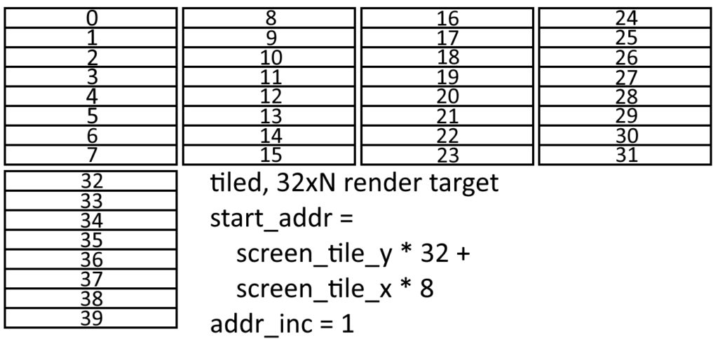
Initialisation mainly caches off the data that triangle setup added to its FIFOs, however some adjustments for tilemode have to be made here. Because writes to render target memory are in terms of eight-pixel screen tile rows, addresses are actually just row numbers. When distributing a screen tile to a rasterizer, the rasterizer needs to know the row address of the first row in the screen tile, and the row address increment to use when going through the rows. For linear, rows that are contiguous in the X direction are also contiguous in memory. This means that the starting row address for a screen tile is screen_tile_y * render_target_width + screen_tile_x, and the row increment is width / 8.

For tiled, all of the rows in a screen tile are stored contiguously in memory, and so the inner tile row increment is just 1. And since there are eight rows in a screen_tile, you see addresses incrementing by 8 as you move across the screen to the next tile in the X direction.
The tile distribution state begins by calculating the target rasterizer from the tile X and Y coordinates, and then checking if that rasterizer’s input FIFO is full. If the FIFO isn’t full, it adds the screen tile row address, row increment, vector of eight edge function values, the B for each edge, and the current tile mode to the rasterizer’s input FIFO. It then moves right to the next tile, incrementing the vector of eight edge function values by 8A, and updating the row start address for the next tile. When the end of a tile row is reached, it moves up one tile, and starts moving left. It continues in this snake pattern until all screen tiles in the AABB have been distributed.
Rasterizers
There are 16 rasterizers, and each is 8 pixels wide. They are essentially wide adders, adding B to a vector of edge function values, checking which pixels are inside the triangle, tiling data if necessary, and exporting pixels and valid masks.
Pipeline
In this section, LR refers to linear rows, or the eight rows (per-edge rows of edge function values) produced by the adder for a screen tile. These are produced in LR0, LR1, LR2 … LR7 order, or the order you’d expect for a linear surface. Conversely, tiled rows are referred to as TR, and are produced by taking as input two linear rows and applying some tiling function. For example, TR0 = Tile01(LR0, LR1) means taking in linear rows 0 and 1, and producing a tiled row in the format TR0 or TR1 expects. There is also a Tile23() for producing TR2 and TR3.
// 0  1  8  9  | 2  3  10 11
// and
// 16 17 24 25 | 18 19 26 27
function automatic FuncRow TileRow01(input FuncRow first_row, input FuncRow second_row);
    FuncRow retval;
    for (int e = 0; e < kNumTriangleEdges; ++e) begin
        retval[e][0] = first_row[e][0];
        retval[e][1] = first_row[e][1];
        retval[e][2] = second_row[e][0];
        retval[e][3] = second_row[e][1];
        retval[e][4] = first_row[e][2];
        retval[e][5] = first_row[e][3];
        retval[e][6] = second_row[e][2];
        retval[e][7] = second_row[e][3];
    end
    return retval;
endfunction
A tiled block is 4×4, so an 8×8 screen tile needs to produce 4 blocks. If linear were the only supported tilemode, the 8 rows of these blocks could be produced in order, but tiled data makes it a bit more complicated. For the purposes of the diagram below, numbers indicate the order edge function values are produced by the adder, with 0..7 being the first linear row, 8..15 being the next linear row, etc.
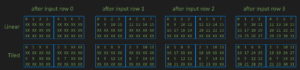
There are two things to note. First, rasterizers create 4×4 blocks in horizontal pairs, over four input rows. To simplify the logic and ease timing, rasterizers process the first four linear rows, building up the first horizontal block pair and writing the resulting rows to four row FIFOs for later consumption. The second block pair is then constructed from input rows 4..7, and also added to the FIFOs. This is fully pipelined, and there is no stall between the creation of the lower block pair and the upper block pair.
The other thing to note is that the stages in which output rows can be determined is different for linear and tiled. Linear can produce a complete output row every clock, while tiling rows requires two different linear rows as input. From the diagram below, you can see that calculating tiled rows 0 and 2 requires linear rows 0 and 1, and calculating tiled rows 1 and 3 requires linear rows 2 and 3.
Stage 0
Stage 0 is where the 24 adds (8-wide row x 3 edges) happen. If this is the first row in a screen tile, the edge function starting values for the screen tile’s first row are fetched from the input FIFO and passed to the next stage, otherwise the row is incremented by B and passed on.
Stage 1
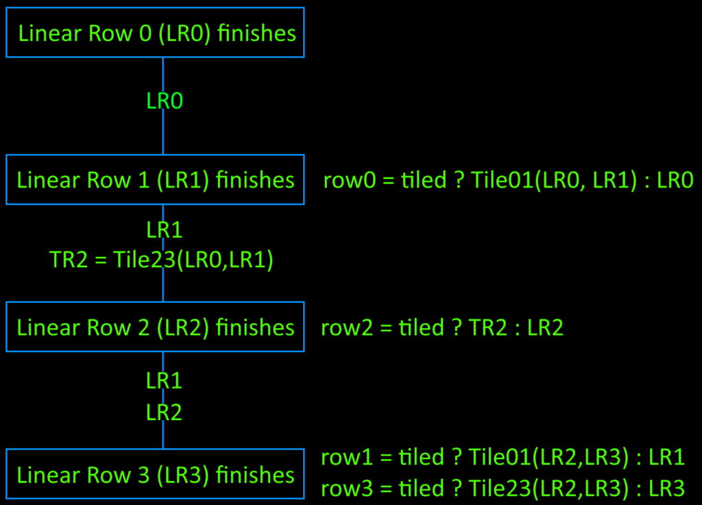
In stage 1, the first linear row (LR0) becomes available, but TR0 requires both LR0 and LR1 to calculate, so LR0 is just passed through to the next stage.
Stage 2
In stage 2, LR1 finishes, meaning I now have the data needed to produce TR0 and TR2. TileRow01(LR0, LR1) tiles the data, and the resulting TR0 is muxed with LR0 as row_fifo_din[0] = tiled ? TileRow01(LR0, LR1) : LR0.
Stage 3
LR2 becomes available here, so I use the previously tiled TR2 to calculate row_fifo_din[2] = tiled ? TR2 : LR2. Both LR1 and LR2 are passed on since they will be needed in the final stage.
Stage 4
Stage 4 is the final stage, where LR3 becomes available, and the remaining two output rows can finally by calculated. This means row_fifo_din[1] = tiled ? Tile01(LR2, LR3) : LR1 and row_fifo_din[3] = tiled ? Tile23(LR2, LR3) : LR3. Because row_fifo_din[3] is the last FIFO to be written, the export block uses ~row_fifo_empty[3] to determine when all four rows of a block pair have been added.
Export
Export reads the four rows of a tile pair from the four row FIFOs, and appends them together into all_rows. This way, all_rows[0] is always the row I care about, and each clock I can just shift all_rows right by the size of one row to get the next row.
For each row, I look at the sign of the three edge functions. If all sign bits are zero, then the pixel is inside the triangle. Rows where all eight pixels are outside are discarded here. Valid rows are sent to a two stage arbiter, where the first stage arbitrates between the four clients in each rasterizer group according to a rotating priority, and the second stage arbitrates between the four groups.
Demo Structure
Because I am a weak human who is afraid to try a test of everything together before I try out lots of smaller targeted tests, the demo is stripped down from the final GPU in a couple of ways. かんにんしとぉくれやす!
- Pixel shaders aren’t hooked up yet. Rather I went for a temporary fixed function type thing where rasterizers export rows directly to memory for HDMI scanout to consume
- Texture units and the texture caches aren’t hooked up in this demo.
- There is one render target, and it starts at a fixed address of 0. Renders to render targets of different size all just alias this area, which is sized large enough for the maximum RT size (640x480x16bpp)
- There is one texture, and its address is fixed to be at the end of the render target area. I know I already said texturing wasn’t hooked up yet, but render to texture is the very next test I want to try
- The final memory fabric is there, but only render target and scanout clients are hooked up.
- There is still lots of perf tuning and balancing of the memory fabric to be done, as right now I am doing some pretty naieve things

In the above image, each of the four rasterizer groups feed into an arbiter that selects a client request from the four attached rasterizers. That request is then fed to the RT group arbiter that selects a request from one of the four groups and passes it to the DDR3 arbiter. The other three DDR3 arbiter clients are scanout, texture read requests, and texfill, with scanout having the highest priority, and texfill having the next highest.
FAQ
- Is this how real GPUs work? I’ve never seen a line of professional RTL in my life, but I am willing to guess the answer is no. It feels like how you’d design something for FPGA architecture is different than how you’d design for ASICs and proper chips, and the scale of what you can do is smaller on FPGAs. Also professional GPUs have the additional advantage of being coded by professional RTL engineers… which I am most certainly not. No seriously, I have no idea if what I am doing is weird, normal, sane, or insane.
- What is the speed of light / expected perf? TODO once I get more perfcounters in there
- Will you add [depth|mipmaps|stencil|compute|cubemaps|depth compression|colour compression|whatever]? If you have features you want me to add, please give me your twitter name and I will block you.
- Will you support Games Pass? Yes, in that a friend once asked me if I intend to make Games, to which I replied “Pass”
- Did you release this blog post on 12月3日 on purpose? Not at all, since 一二三でゲームが変わらへん
- Really? Are you sure? #行くぜ、一台へ